Text screens could get by with just a simple cursor that inverted the character beneath it. This is the standard method with text-only displays.
Cursors that can highlight areas of text are more of a problem.
Graphic cursors are even more work. A single pixel cursor is not very visible. Full-screen cross-hairs are easy to implement in hardware, but look rather intrusive and are now out of fashion. The early GUIs used the cursors commonly in use today.
A fair number of pixels are required to draw a graphic cursor, typically 16 x 16 = 256 pixels. Not a vast number, but processing them in software for a rapidly moving mouse is a significant chore. Early PCs spent a good fraction of CPU time on this, and PC graphics chipset manufacturers soon added hardware assistance for cursor management. This effectively provided what was often known as a 'hardware sprite' in 6502 based machines, except in this application it was not used for a game-play object.
Screen and cursor data have to be available to the video circuitry simultaneously. The screen data is in the main RAM, so the cursor has to be stored inside its own RAM. Fortunately it is possible to implement such RAM inside the chosen FPGA.
Kees van Oss implemented a cursor on the Atom, although using a lot of memory.
Looking at the PC world, many graphics chips are capable of providing up to 64x64 pixel true colour cursors. In practice, most cursors seem to be 16x16 and monochrome. The manufacturers are probably just "keeping up with the neighbours".
The first stage was to create a 'cursor window' signal. This is asserted in the 16x16 square that is to contain the cursor bitmap. There are two counters for the X and Y axes, each creating a window signal for an axis. These are reset by the sync pulses, and therefore start counting from the top-left margin. This differs from the normal convention where the top-left displayed pixel is the origin.
The advantage is that the cursor can be moved outside the text/image display area and into the margins: the whole cursor is visible even when its top-left corner is over the bottom-right pixel of the image. You can see this is not the case with a PC cursor. A second benefit is that a cross-hair cursor fully extends into the margins.
Clicking in the margins might be used to navigate between screens in a 2-D tiled pattern.
The cursor is superimposed on the screen by inverting the physical pixel colour bits. For example a monochrome screen with green pixels on a black background is inverted to magenta pixels on a white background.
A practical issue is that video signals should be 'slightly blacker than black' for a short while after the sync level. This allows the TV to know roughly where the 'black' level is. In practice one can get usually away with black. The ZX81 has a white margin immediately after hsync, and usually gets away with this apart from slight 'tearing' on lines at the top of the screen of some TVs.
On the TV used in testing, having the cursor asserted immediately after the hsync caused the lines to gradually skew to the right, making the text at the cursor Y position slant to the right. Lines below the cursor are upright but shifted to the right. Clearly this is unacceptable so the final design will address this problem by forcing the correct level just after the sync pulse.
A convenient technique is to have two bits per cursor pixel. The obvious way would be to have one bit for the pixel colour (e.g. black/white) and another to select whether that pixel replaces the background image or not. A cleverer way is to have the background ANDed with one bit and XORed with the other. The background can then have four actions: to leave unchanged, to invert, to set, or to clear (== set and invert).This is the way Kees van Oss implemented his cursor circuit.
Setting/clearing the physical colour bits limits it to either black or white. So a further refinement might be to implement the cursor with multiplexers:
| Bit 1 | Bit 0 | Action |
| 0 | 0 | output <= display pixel unchanged |
| 0 | 1 | output <= display pixel inverted |
| 1 | 0 | output <= cursor pixel background |
| 1 | 1 | output <= cursor pixel foreground |
The cursor can still only have two colours, but now you can control what they are instead of having to settle for just black or white.
It is fairly simple to have the cursor image in ROM, but making it user definable requires RAM shared between the CPU and VDU. This has the same problems to solve as the main display RAM sharing.
One way to do this is to give the CPU priority. This isn't such a problem as it is for main video RAM, because cursors do not change shape as often. When they do, you don't want the change to happen part way through a video frame - that allows half-changed cursors to appear. So it isn't a problem restricting cursor change to the non-display periods. In fact any non-cursor time will do, so simply waiting during the cursor's scan lines should be fine.
A second way is to interleave access in the same way as the main display RAM. The cursor data must be available to the VDU at any pixel boundary, unlike the main screen data which need only be available at display byte rates. The main screen latches the display byte during the CPU access phase, and it seems sensible to have similar latching for the cursor data byte. This can be latched at a suitable VDU byte-access phase, then read out and mixed at the required pixel edge.
The cursor position is changed by writing to a pair of latches. These are only sampled at the top-left of each per frame, ensuring that the position is constant throughout each frame. It is not possible to modify the position during the frame, to make the cursor appear in several places within a frame.
| A single crosshair cursor is easy: | 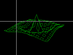 |
| A second crosshair is simply another instance: | 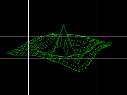 |
| The two can be clipped to form a rectangular edge: | 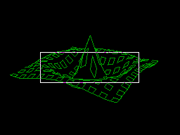 |
| or merged to form a filled rectangle: | |